The two noise contributions in the PFD/CP:
- PFD jitter
- noise in the output current of the CP
The PFD noise will all be in the charging and discharging edges and will be independent of how long the CP is on. However, the total noise produced by the CP will be proportional to how long it is on.
Two current sources provided to loop filter by the CP: one is pull-up current and the other pull-down current. Which one is activated depends on whether the edges on the reference input lead or lag those on the feedback input signal. When edges from PFD or UP/DOWN signals occur simultaneously, both the pull up and pull down current sources will turn on for a very short period of time. From an output current perspective the pull up and pull down currents will act to cancel each other and so the effective output current is zero. (If the current is not zero, what happens?)
And both current sources will be contributing uncorrelated noise (“Uncorrelated” means that the values are independent; that is, knowing one value provides no information about the others.) to the output while they are on. Thus, it is best to characterize the noise of the PFD/CP with simultaneous edges occurring on both the reference and feedback inputs. The output should be connected to a current probe (ideal voltage source) that is biased to present the expected voltage to the output of the CP.
Using Cadence PSS+Pnoise analysis, the phase noise of the PFD/CP can be obtained. Which is the right sweep type correct: relative or absolute?
If setting the sweep type= relative, the actual sweeping frequency is f1+n*Fpss to f2+n*Fpss, where f1 and f2 are the defined sweeping range and n is the relative harmonic number, Fpss is the PSS fundamental frequency. The benefits of the relative sweep is when simulating oscillators, because you want to look at the noise skirts around the oscillator frequency, but you don't know the oscillator frequency (accurately enough) before running, so letting PSS find it itself, and doing a relative sweep makes sense.
What about absolute sweep?
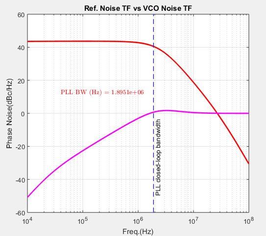
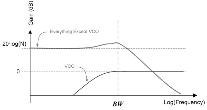 > noise transfer functions of the reference and VCO
Therefore, it is useful to show the PLL bandwidth in the plot.
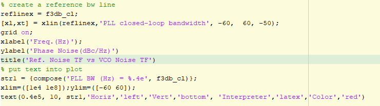
New version Matlab provides a 'xline' function, vertical line with constant x-value, to plot a line in a plot.
> noise transfer functions of the reference and VCO
Therefore, it is useful to show the PLL bandwidth in the plot.
New version Matlab provides a 'xline' function, vertical line with constant x-value, to plot a line in a plot.
 If you don't have the new version of Matlab, you can use another m function ([Link](https://wwem.lanzouq.com/iSonk1hpecmh)) to add a reference line.
Example code is shown below:
If you don't have the new version of Matlab, you can use another m function ([Link](https://wwem.lanzouq.com/iSonk1hpecmh)) to add a reference line.
Example code is shown below: